

Labthink TOY-C1 Package Oxygen Permeation Test
Source:
Viewer:1480
Issuing Date:2006-11-16
Click to download!
Abstract:Test of package oxygen permeability has been a great problem in packing industry. Presently , lots of evolvements have been reached.
Keywords:
package
, oxygen permeability
, oxygen transmission rate
, packing
Based on the standards of ASTM F1307, Package oxygen permeability testing has been briefly introduced in one of the former articles. This article is going to provide a detailed procedure of package oxygen permeability testing for the first self-developed oxygen permeation test instrument of China, TOY-C1.
1.Preparation
Prepare one bottle of high pure nitrogen and one bottle of pure oxygen of 40L respectively (oxygen gas can be omitted if the test is going to be carried out under lab environment.). Connect air supply pipe and escape pipe of the instrument properly. The following procedure will be preparing specimen as well as preparing the accessory, package and oxygen shield for attachment.
1.1prepare the specimen
The TOY-C1 components for package oxygen permeation testing can meet the following requirements: inner diameter of bottle mouth is greater than φ 13mm and external diameter of bottle mouth is less than φ 50mm ; when tested in an oxygen concentration of 100% ,d iameter of bottle body is less than φ 120mm and the height is less than 360mm. There is no restriction on bottle dimension under laboratory test environment. Sample preparation, which plays a crucial role in whether the test is successful or not, must be carefully performed.
prep ration
Make available for the package (there should be no disrepair and scuffing on the package and the package should be dry and no water dripping inside it)alcohol tampon , vacuum grease , package frame , glue , glue container and scale.
1.1.2 Operation procedure
First, clean groove part of the bottle with alcohol tampon and airing it. This procedure cannot be omitted because greasy dirt in the groove part may cause disengaging of the filling glue. Next, prepare the filling glue according to the method provided by Labthink (glue container and scale are needed). Please pay careful attention that the filling glue should be fully intermixed in the process of preparation in case that the filling glue is not able to coagulate in a long time. Then put the package bottom down (dry inside) into bottle bracket and fill the glue into groove (assistant tool can be used). The glue should finish filling within one hour of its preparation.
Put the encapsulated package at room temperature for about 24 hour, the glue can be completely solidified. But the solidifying time may be prolonged if the room temperature is too low or the glue was not fully intermixed in the process of preparation. By now sample preparation is finished. Figure one is some completed package sample.
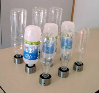
Completed Sample
1.2 install the test components
Take off the three upper cavities, and clean their working surface of the three lower cavities, additional lower cavities and bottom surface of the bottle bracket with alcohol tampon. Make sure that all the O- shape sealing loops are in good condition. Then the additional lower cavities can be installed according to the method provided by Languang. Fasten the additional lower cavities and be careful not to backup their gas circuit.
Install package to the additional lower cavity. Be careful not to scuff bottom surface of the bottle bracket. Fasten the bottle bracket using accessory appliances to secure it to the additional lower cavities.
Bottom surface of the oxygen shield should be cleaned with alcohol tampon before installation. Then cove it carefully on the package. Also be careful not to backup its gas circuit. Tighten the bolts after examination. When tested in an oxygen concentration of 100% or in oxygen with a special concentration (the required oxygen concentration is not equal to that of the lab environment), installation of the oxygen shield is needed. But if the test is performed in lab environment, oxygen shield will not be needed.
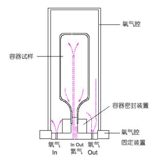
Fig 2 is the finished installation of test components.
2. Test procedure
2.1purging the system
Purge upper cavity of the system with nitrogen gas of about 80ml/min(purging operation of upper cavities and other operation for cavities is not needed if tested under lab environment ), at the same time purge the lower cavity with nitrogen of about 30 ― 40ml/min. The purging period is determined by the volume of the package. Labthink has offered some empiric values to help operators determine the purging time. Regulate the flow rate of nitrogen carrier gas of upper and lower cavities to a value of 10 + 0.3ml/min when purging time is up a nd divert the flow of nitrogen carrier gas of lower cavity to the sensor . Observe output value of the sensor―‘system zero point 'value. Maintain this configuration until the variation of the zero point value does not exceed 1ppm within t wo hours. Note this value and record as zero point value.
2.2 test
Stop the nitrogen gas to upper cavity. Then divert oxygen gas with a flow rate of about 80ml/min to the upper cavity and maintain that rate for about five hour. Later regulate the flow rate of oxygen gas to10ml/min. The slow increasing of the sensor output current is an indication that there is oxygen transmitting into the inside package. When the oxygen quantity maintains at a certain value and the variation does not exceed + 5 % within 10 hours, it can be considered that the transmission has approached an equilibrium and the quantity of oxygen gas passing through the package is the test result.
During the testing, whether the flow of nitrogen gas for the lower cavity is appropriate will have a direct influence on the test result. That is why the instrument has a very high requirement for the controlling device and the flowmeter of nitrogen gas flow rate. The nitrogen gas flow of 10 + 0.3ml/min that is needed for lower cavity of TOY-C1 completely conforms with the specification of ASTM F 1307. Furthermore, the high precision A-1 product adopted in the flow rate regulating can completely ensure the regulating accuracy. But it should be noted that too big a regulating range is not allowed for nitrogen gas flow rate of lower cavity.
3.Finish testing
After testing, close oxygen gas source to stop supplying oxygen to the upper cavity and adjust the system to purging condition (nitrogen gas to lower cavity bypass the sensor). If the instrument will be use for testing in the near future, in order to prevent the air from backward permeating the system, the nitrogen gas can be adjusted to a flow rate of about 5ml/min to supply the system over a long period (It is calculated that one 13MPa, 40L bottle of high pure nitrogen gas can supply the system for one year if it purging the system with a velocity of 5ml/min). An alternative method is to close the sealing valve and then carefully remove the testing components. Be careful not to scuffing the sealing surface of each component and keep then them properly.
4.Characteristics of the instrument
The self-consuming oxygen sensor adopts by the instrument makes the test cost a little more expensive than that of the differential pressure method. But the oxygen sensor of TOY-C1 has a service life of twelve to thirty months under normal condition, which is one or two times longer than that of the similar products abroad. That can correspondently reduce the test cost of the instrument users.
The number of sample can less than three. When there is only one sample, the instrument can perform regular test if the ‘blank package sample' of the instrument is prepared for attachment in testing cavity strictly according to the film test method and then modify the test number of system configuration. By this way, the difficulty of sample preparation is reduced; the service life of the sensor is prolonged. Moreover ,it has enlarged the measuring range of instrument ,which make the upper limit of instrument measuring range reach 10ml/pkg ・ d.
The mechanical and pneumatic design has brought great convenience to the use of instrument. For example, the test process will not be affected by power supply. When losing power, the only influence is that the software cannot be used to control the system. So the instrument can be used in places where the power supply is timing or is limited while the test process will not be influenced. Similarly, if the software is not needed in the test process and also if the data transmission is not required, power supply for the instrument can be cut off after regulating the flow rate of lower cavity properly.
Title:Labthink TOY-C1 Package Oxygen Permeation Test
Link:http://service.labthink.cn/en/article-Permeation-info-110118122.html
Labthink Copyrights. Please do not copy without permission! Please indicate source when copy.
Link:http://service.labthink.cn/en/article-Permeation-info-110118122.html
Labthink Copyrights. Please do not copy without permission! Please indicate source when copy.
Member Registration and Login In
| If you are already a member of us, please login in! | If you are not a member of us, please register for free! | ||
·Forget password? |
|
・Terms and Conditions If you have questions, please phone 86-531-85811021 |
|