Laboratories


1. User Demand
Pour into the water vapor transmission cup with distilled water. Seal the cup mouth with the specimen. Then, turn the water vapor transmission cup upside-down, so that the cup mouth is downwards. Test the water vapor transmission performance in this state, that is, distilled water directly contacts testing specimen on the upper side. This method is called inverted cup method.
2. Requirements in the Standard
The demand is similar to the water vapor transmission property testing regulated in GB 1037, Test Method for Water Vapor Transmission of Plastic Film and Sheet – Cup Method; the only difference is that the specimen in our test is below and in direct contact with the liquid.
3. Test Design
3.1 There exists the possibility of leakage of the distilled water. The leakage would be the indication of test failure. Moreover, the leaking liquid would damage the electronic parts of the instrument and be unable to operate. Therefore, it’s of extreme importance to avoid leakage.
3.2 During test, air flow on the surface of the specimen should be guaranteed so that the water molecules can be timely carried away.
4. Testing Procedure
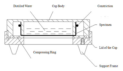
4.1 in order to realize the testing demand and prevent leakage, we reform the structure of the water vapor transmission cup as follows:

Fig 1: Water Vapor Transmission Cup Structure
The procedures for specimen clamp are as follows: cup mouth is placed upwards, pour the distilled water inside and place the specimen. Then, install the constriction and compressing ring, and screw down the lid of water vapor transmission cup. After installation, put the cup in inverted position as shown in Fig. 1.
? In this testing structure, if the edge of the specimen is higher than the water level, there would be no leakage even if the sealing is imperfect.
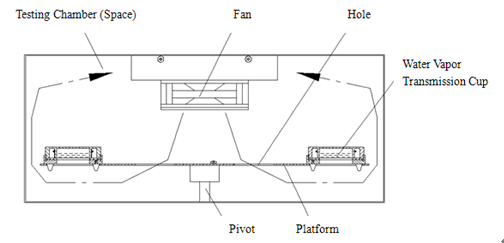
? There are three cone-shaped supports at the lower surface of the cup lid. They can guarantee sufficient space for water molecules to be taken away by the gas flow, and they can function as the positioning tool when the cup is placed onto the platform inside the instrument as shown in Fig. 2.
? After clamping, the specimen should be placed aside for at least half an hour so as to confirm the existence of leakage.
4.2 In order to guarantee the smooth gas flow.
Drill holes on the platform so as to guide a cycling circuit for gas flow and guarantee flow speed.

Fig 2. Structural Drawing of Testing Chamber
5. Conclusion
With the above reform, it’s proven to satisfy demands.
| If you are already a member of us, please login in! | If you are not a member of us, please register for free! | ||
·Forget password? |
|
·Terms and Conditions If you have questions, please phone 86-531-85811021 |
|